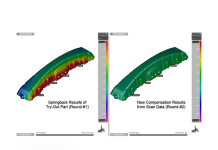
Springback in sheet metal stamped parts is an often discussed topic. However, springback of closed-section tube-hydroformed parts is addressed less often. One possible reason for the delayed focus closed-section parts may be that tube-hydroformed parts achieve desirable strength-to-weight performance when made from mild steels, which tend to have less springback variation than higher strength conventional assemblies. The natural tendency of hydroformed parts is to be very stiff, with marginal residual stress gradients, also contributes to less severe springback variations. Thicker, lower-strength components with closed sections have less springback than conventionally stamped High-Strength Steel parts and assemblies. This can make it seem that the springback in tube-hydroformed parts can be reasonably controlled. Tube-hydroforming professionals had fewer issues with springback — until now.

Tube Hydroformed engine cradle will have more springback when using down gauged HSS
With increased application of High-Strength Steel (HSS) and Advanced High-Strength Steel (AHSS) for tube-hydroformed parts, springback of tubular parts is now moving into the spotlight. One of the design advantages of the integration of closed-section tube-hydroformed parts — their increased stiffness when compared to conventional stamping — magnifies the springback challenges facing tube-hydroforming. The stiffer closed-section components cannot be “clamped into submission,” and therefore springback in components can create very significant assembly issues.
Additionally, springback in closed sections creates some new challenges beyond the experience of sheet metal stampers and their approach to dealing with springback. The elastic recovery of different areas within the tubular part can lead to deformation and distortion of the part, which may not seem intuitively obvious. When observed, springback in the tubular parts can be recognized as three distinct types or modes of springback.

3 different modes of springback could occur simultaneously
The interplay of these three modes of springback presents many challenges to the methods employed to address and counteract the springback, such as how and where to apply the geometry changes to the tooling to counteract springback for tubular parts. Unlike sheet metal stamping where springback modifications are applied to mating halves of tools, compensation for tubular parts is not as easily centered about a single point in space nor is it uniformly applied to upper and lower halves of the tools.
Complexities in dealing with issues like how much of the springback observed should be applied to the pre-bend tube and how to apply that compensation introduce another issue. Because tube bending is applied incrementally, the effect of springback is potentially applied differently: is the observed springback is at the “tip” of the tube versus the “tail”? Would the effects of springback be the same if the process for forming the tubes was altered? Should engineers use different process to resolve?

Springback in the pre-bent tube
Is the deviation in any portion of the tube caused by translation or twist, or a little of both? How much rotation or twist is required to compensate each bend? Should compensation alter the size of the bend disk, or the number of degrees bent? Will altering the order of the bending operations, for nonsymmetrical tubes parts, alter the springback effect and is that an appropriate countermeasure for reducing springback effects?
Another challenge is the complexity of machining and maintaining the tools to accommodate the springback compensation. With sheet metal stamping, springback compensation is applied to the upper and lower tools in equal measure. If the lower die is cut to accommodate compensation, then the upper die must match to some degree. However, in tube-hydroformed parts, the upper and lower halves of the die each touch completely different portions of metal and therefore are not mating halves of each other — not an insurmountable challenge, but another level of complexity in the machining of tooling surfaces.

Hydroform tools can be built using inserted sections to minimize wasted machining time for springback (source image Schuler Group)
Tube-hydroforming industry leaders like Schuler Group have invested in innovative solutions to address the springback in hydroformed parts and processes, such as upgradeable production tools that use inserts for ease of recutting without the need to build and maintain a separate prototyping tool. This aids activities such as in-press adjustments and compensation, but is still less desirable than addressing springback before any tooling is created.

Initially, all tooling corrections were performed on the production/prototype tool
The use of CAD models in FEA/CAE to predict the springback in tube-hydroformed parts enables a reduction in the number of iterations needed for tooling adjustment in-press. However, there is an increase in investment for FEA/CAE work and CAD. This provides some time savings; however, the tendency to shortcut engineering development in favor of starting manufacture of production tools limits the number of iterations the designers will evaluate. Additionally, without commercially available springback compensation tools, compensation must be manually developed and modelled in CAD, a time-consuming task, sometimes of questionable value. Each compensation loop is little more than an educated guess by the designer on how to implement the changes to the tooling geometry.

Conventional practice is to compensate the tools within CAD, then recut tools as needed
To further reduce delivery time for tube-hydroformed parts, the creation of compensated (morphed) geometry and the computation of springback effects should be streamlined. If you apply the compensation to the tooling geometry and tube bending process in the same application as the forming analysis, springback computation will enable users to reduce both CAD work and expensive in-press modifications.

Software innovation allows compensation and evaluation in same application, reducing CAD rework and recutting
Find out in following posts how AutoForm-Hydro2016 addresses the challenge of springback in tube-hydroformed parts.


