- Have you ever defined a hot forming process virtually?
- How do you determine which design and process parameters are required for the production of a high quality hot formed part?
Finite Element Analysis (FEA) is an appropriate tool to engineer parameter settings and their impact on the final process definition. The use of Finite Element Analysis, already commonly applied to conventional stamping of sheet metal parts, becomes even more crucial to the design and validation of the hot forming and press hardening processes. Simulation is needed to validate the feasibility of the forming process—no splitting or wrinkling of the sheet—and to validate that after cooling the material possesses the required final component strength. Two major process variants of hot forming processes are widely known and industrially established—Direct hot forming and Indirect hot forming.

Hot blanks loaded into die after furnace pre-heating. Source: Automotivemanufacturingsolutions.com
The direct hot forming process is a three-stage approach. After heating up to 950 °C a blank is transferred to the pre-conditioned forming tools. Then the part is formed in an austenitic state. Afterwards the part is quenched in the colder tools. Applying a defined tonnage or engineering a specific gap between tools and the blank heat transfer conditions are adjusted. During this process stage the temperature in the blank drops from around 950 °C initially down to 200 °C. The average temperature of the tool in use is maintained near 80 °C. During this stage the transformation to a martensitic phase is driven by controlled heat transfer conditions that lead to characteristic cooling curves and therefore to final values for yield strength (YS) and ultimate tensile strength (UTS). Trimming the blank can be executed either directly in the tool or by means of a subsequent laser trim operation.

Direct hot forming production schematic
The indirect hot forming process is characterized by an additional process step. In contrast to the direct hot forming, the sheared blank is preformed in the initial ferritic-pearlitic state prior to heating. Then the preformed panel is heated up to the forming temperature and thus converted into the deformable austenitic state. Subsequently, calibration (or restrike) process is carried out and the panel is quenched in the calibrating tool to 200 °C. The final trim is mostly done by means of a laser or can be also achieved by integrating tool segments in the calibration tool.
In both cases the forming and calibration tools respectively are designed to preventing non-homogeneous local cooling, to place the blank or pre-formed panel in the tool and keeping the panel in the right forming position. Such supporting solutions can be pilots, pads or fold-away tool parts. The goal is to validate that the engineered tool and the forming conditions are capable of delivering the specified product; the metallurgy of the deformed and quenched panel achieves the appropriate metallurgy for the specified end product performance.
Considering for example the direct hot forming process, an entire set of parameters can be defined whilst engineering the details of the process. Appropriate measures are used to describe the interactions between heated blank, cooled tool and ambient environment. Table 1 below gives an overview on definable influencing base parameters and their units.

Table 1: Hot Forming parameters design, production line, and environmental constraints
This sample set of parameters serve as input data for the calculation of the deformation of the sheet, temperature history in the deformed panel, the phase transformation, and thus the final properties after hot forming and quenching. Heat transfer between blank and tools is a function of applied pressure and tool contact, which describes the real heat transfer conditions in an accurate way. Engineering and simulation of more sophisticated hot forming technologies like the production using Tailor Welded Blanks, Tailor Rolled Blanks or Tailored Tempering additionally complicate the engineering process.
Limitations of proposed production lines and their ability to load blanks into tools, press closing speeds, and unloading of tools can govern the process engineering decisions, as well as part design. Inclusion of tooling design elements such as die face geometry, engineered gaps, supporting tools, enforced tool temperatures, and quenching time further govern the definition of the product and stamping method. Target constraints such as part temperature after process, might highlight the need for extended conveyor lines to ensure sufficient cooling to allow parts to be handled.
The set of considered parameter can be easily extended to include further definition of intended part design and process design. The chemical composition and the mechanical properties of the micro-alloyed boron steel, the shape of the blanks can be used as design variables. The designed combination of inputs can be validated with respect to the process outcome – an engineered manufacturing process and an ideally conditioned part. With such a potential range of variety of input parameters all influencing the output, it is clear that a systematic approach to define and evaluate the process parameters is necessary to avoid endlessly iterating different combinations of design and production line constraints.
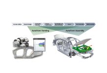
AutoForm offers solutions to engineer hot forming processes and evaluate the impact of production line limitations on final product. Even prior to having an operational hot forming line, it is necessary to define parameters and performance ranges prior purchasing equipment. AutoForm-ThermoSolver can be used to validate such processes in detail. Additionally, applying Systematic Process Improvement (SPI) with AutoForm-Sigma enables the method planning engineer to determine optimal parameter ranges in an efficient way. In this methodology, design variables are defined and will be varied over a specified range; the influence and sensitivity of each parameter can be evaluated, easing and accelerating decision making.
The capabilities of AutoForm Solutions with respect to the set-up of hot forming processes will be key topic during our participations in dedicated conferences in the Americas. AutoForm Engineering will be present on May 18 to May 22 at the 8a COBEF in Salvador, Brazil and on May 31 to June 3 at the CHS2 2015 in Toronto, Canada. We encourage you to come and meet us at the conferences. Please, bring your thoughts and questions regarding sheet metal forming simulation! We would be pleased to have the opportunity to discuss related topics and to share our expertise with you.
Links:
- http://www.autoform.com
- http://www.cobef.com.br/ May 18 – May 22, 2015
- http://www.chs2.eu/ May 31 – June 3, 2015


