How to ‘Read the Signs’ in Secondary Tool Compensation
In the sheet metal forming industry the compensation of surface as countermeasure of the springback effect of the metal part is a practical and common technique used since “the dawn of time”.
Although the phenomenon is well known, the research and the definition of the best practice (or best strategy) that should be adopted to compensate the tool surfaces to produce a certain part, challenges all engineering departments during the Process Design phase of the metal forming process chain.
A lot of questions soar while looking for the more effective strategy. Which tool must be compensated and based on which measurement? Should we use the measurement of the springback right after the operation of the involved tools or the one at the end of the entire process? Should the entire springback be “recovered/balanced” and have the part within tolerances right after the drawing operation?
And what about pad and post of the trimming and flanging tools: how should they be compensated? Should they be compensated at all?
Well, we all would like to answer those questions once and for all different cases but unfortunately there is not a single answer for all parts; tool compensation is one of those trial-and-error iterative process that takes time and efforts.
Since “the” single answer does not exist it needs to learn how to “read the signs”, meaning how to interpret the data and decide to go in a certain direction rather than another one because saving loops of the above mentioned iterative process means saving time and money while reaching an higher quality / stability of the entire process.
In this blog post we want to discuss the questions regarding the compensation of the secondary operations tools. When and how we at AutoForm suggest to apply the so called “Draw-shell” compensation: in few words how to “read the signs”.
Before doing that let’s refresh the concept of the “Draw-shell” compensation: what does it mean?
To better answer this question I think that a comparison with the “standard” compensation is more effective.
The “standard” compensation method consists in the modification of the surface of the tools in the opposite direction of the part springback.

Figure 1 – Springabck effect after Drawing OP
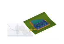
Figure 1 shows an example of the springback principle: when tools are closed the sheet has the same shape as the tool (which we assume is “nominal” at the first loop). When tools open the part springs back upward (in our example case) and what we get is a part more or less far from the “nominal” or “target” one.
Because we want to have the part as close as possible to the nominal once it sprung back, (within dimensions tolerance and with a certain quality) we modify the shape of the tool in opposite direction of the springback result.

Figure 2 – Example: Compensation of the Drawing OP tools
What we actually do is inverting the springback result and we apply the resulting material movement to the surface of the tool to generate the compensated one (see figure 2). In “reversing” the springback result we may use the same amount or just a portion of the springback result: we define what is called the Compensation Factor.
For the Draw-shell compensation we do not reverse the springback result to compensate the tool but we actually use it as it is, same direction and amount, because we want the tools (pad and post) of the Trimming OP for instance, having exactly the same shape as the sheet after springback.

Figure 3 – Draw-shell compensation concept
Draw-shell compensation technique is used to avoid the restrike of the sheet while cutting and piercing. It is better to avoid restrikes because the part may undergo to additional unwanted plastic deformations that can create both dimensional (it may affect the springback of the part after the OP) and surface quality issues.
When and how to decide if the trimming tools, for instance, should be compensated with drawshell?
We at AutoForm have implemented some result variables in AutoFormplus that are able to highlight if the contact with the tool at closing time-step is producing plastic deformations to the sheet that are not supposed to occur.
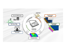
First of all we, at AutoForm, suggest (strongly encourage) the designers to simulate the entire process by using parameters value as close as possible to reality when preparing for compensation. This means that all movement of the sheet must be simulated as summarized in the figure below.

Figure 4 – Full Process Simulation settings
Let’s assume we have a 2-OP process which includes a drawing and a trimming station.
In drawing station (D20 in the figure above), we have to simulate the gravity of the sheet, the tool closing, the drawing of course and then the stress release that occurs in the stamped sheet to detect the resulting shape (springback measurement right after drawing).
Then, in simulation just like in reality, the sprung back sheet moves forward to be placed in the next operation tool (T30 in our example). In order to understand how to compensate T30 pad and post tool it is important to simulate the positioning, locating and closing of the tool. We can really understand what happens by evaluating some result variable at this time-step: how the sheet fits on the post (locating) and if the pad of T30 restrikes the sheet (during closing) before the actual trim occurs.
When the sheet is misplaced or does not fit correctly on T30 post, a restrike will occur as shown in the animation below.
Now it is important to evaluate how much this affects the surface quality and the springabck of the sheet right after the trimming. The final evaluation is performed at stage M100 where we actually place the final part in the virtual measurement device and we detect differences with the target or “nominal” geometry.
In figure 5, instead, an example is displayed. The image on the left shows the result of the undesired plastic deformation that occurs along some radii if the tools used in T30 have the nominal size and shape (no compensation occurred yet). The image on the right shows the same variable result when Drawshell compensation has been performed.

Figure 5 – Effect of Drawshell compensation on unwanted plasticization
In the picture below we can compare the results of the springback right after the trimming operation: on the left we have the scenario where no compensation of T30 tools has been performed while on the right the results obtained when one loop of drawshell compensation has been performed.

Figure 6 – Effect of Drawshell compensation on Springback
In the picture above we can see how in the area on left-upper corner of the part the distance from the reference geometry (“nominal”) has been reduced quite significantly, and also in the mid area the distance is more uniform.
Additional parameters (such as, but no limited to, smoothing factor, regions where apply the compensation, the way how springback is measured, etc..) must be considered when setting the simulation and to apply this compensation strategy, which, by the way, can also be applied more than once.
The scope of this post of course is not to “train” users or try to completely fulfill the requirements of such a complicated topic but it is rather pointing out the importance of using this approach and what kind of result you can achieve by using it.
For further questions we invite you to get in touch with the local AutoForm support team who is glad and able to transfer all knowledge to you, helping you applying these principles and evaluate the outcomes directly on your project.
Gianfranco Ruggiero, PM
Markus Avermann, TPM


