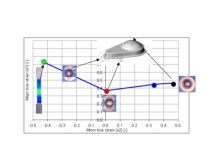
In Finite Element Analysis, it is common to treat the metal restraint due to draw beads as numerical factors applied along a curve or set of curves. The use of these factors makes defining boundary conditions simple and computationally effective.
- Need to increase material flow? Decrease the restraint factor
- Want to tighten up the material flow? Increase the restraint factor
The application of a line bead restraint offers efficiency as it eliminates or at least greatly reduces the computational costs associated with running 3-D geometrical beads and eliminates the need to make any CAD adjustments if additional iterations are necessary to arrive at a safe result.

Adjusting the forming of a part may require editing of countless bead shapes
However, without a reference to the geometry of the bead, engineers are often unable to relate the restraint to a meaningful geometry to be used in building the draw die. Tool and die makers haven’t had a drawbead magic wand that could translate a bead restraining force factor into an appropriate geometry — until now.
While not really magic, the adaptive drawbead used by AutoForm enables users to define a bead geometry profile, which is then used to restrain the sheet metal. The adaptive line bead estimates the restraining force on the sheet metal as if material were sliding through the bead profile, instead of a constant effective line force as was common before the innovation of adaptive line beads. The use of an adaptive bead relates the bead shape to an effective restraint; additionally, it is adaptively responsive to the changes in the material strength, lubrication effects, and thickness in each time increment of the simulation.

Adaptive line bead profile, relating bead geometry to the effective bead restraint for material grade and thickness
As material slides through the bead during the forming process, the bead behavior continuously adapts to the expected condition of material sliding through the profile shape. The restraint and uplift forces are exerted upon the sheet and the tools throughout. By computing the effect of specific geometry, like inclination of the binder surface, thinning in the sheet, and material plastification the performance of the bead is continually adapted for very little computational cost, compared to using geometric beads through the entire process.
Engineers can then use the profile bead geometry (bead height, groove radius, bead radius, etc.) to adjust the material restraint. This method is more parallel to the practice on the die room floor and is more applicable to those with practical stamping experience. Now, if the simulation is successful, the engineer has a well-defined bead profile that can be used as the basis for creating the 3-D tooling for the draw die.

Outer sheet metal Draw-OP engineering relies on drawbeads to achieve stretch requirements for quality stamping
However, when the simulation result indicates that process changes are needed in order to pass evaluation, the draw bead will often require modification. Using the adaptive bead simplifies this adjustment by eliminating the need to fully model the bead in CAD, but the engineer must still try to define how to adjust the bead shape to achieve a desired reduction in material restraint. The engineer/analyst must now decide which bead attribute to adjust to effect an increase or decrease in metal flow. This leads potentially to a significant slowdown in the engineering process, as the engineer finds himself with several geometry inputs that need to be controlled to reduce the material flow. Additionally, many might recognize that there is a recommended limit to how much we might want to adjust one bead geometry parameter before adjusting certain others.
When the force in a draw bead needs to be reduced, is it best to adjust the bead height (H), radius of groove (Rg), or radius bead (Rb). Oftentimes it is preferable to try to minimize any adjustment to bead height until the radii have been sufficiently adjusted. Then, a small change to the drawbead height can be made, which can then be followed by additional bead radii or groove radii changes. For the illustration shown, drawbead height (H) is highly influential; any small change in bead height will likely trigger very large changes in material restraint. In order to provide a high degree of control, perhaps the strategy is to address the bead height only after several reductions have first been attempted in the bead radii or the bead groove.

For this discussion, binder area is presumed fully spotted and gap controlled with bead as sole control of material flow
To further aid in the development and validation of the drawbead, the drawbead reduction strategy enables the adaptive drawbead to reflect the potential combinations of changes to the bead geometry as the strength of the bead is reduced. Through the manipulation of a single value of the bead reduction, a number of tooling geometry changes can be achieved, in an order defined by the engineer in advance.
By using a drawbead reduction strategy, it is possible for the process engineer to allow for minor or major modifications to the drawbead restraint and for capturing the geometry changes in whatever manner is recommended for their organization.

As users adjust the reduction strategy value, the geometry changes proportionately
Now the engineer has a very controllable way to adjust the effective restraint on the bead through the use of a single numerical parameter, which in turn adjusts a potentially broad palette of geometry changes to the tooling –without having to return to the CAD model repeatedly in order to evaluate the effectiveness of the new bead geometry.
Drawbead reduction strategy assures that geometry of the bead profile during engineering or tryout troubleshooting can be adjusted according to norms established by the engineer/analyst. Bead profile changes are achieved through the adjustment of a single value, further enabling systematic process improvement during process engineering and tryout support.


Hellou,
thank you for this article. I have one question. How do you mean, or you experience with the forces and restraining factor. In reality we had have experiece that restraining factor in reality process is bigger than simulation. And sometimes we need higher forces for emboss of drawbead than forces computed from simulation. It is influence of drawbead geometry – clearance ets… It is any recommendations?
Jakub,
Thank you for reading the post and your comments.
There are many reasons why the effective restraint from simulation can result in different forming effect once the die has been cast, machined, assembled, and built. Whether or not it is higher or lower is something that cannot be measured (there is no technology to measure the effective restraint during forming in the real dies. That the setting force (or force to emboss the bead which correlates to “uplift force” might be higher than expected from simulation does speak to some potential differences between the “as-engineered” tooling conditions and the “as-built” or tryout conditions.
you mentioned already one potential root cause, differences in clearance of bead geometry. There are many differing opinions on die construction regarding the machining and fitting of beads and those differences have in our experience often contributed to the difference in setting force (and by extension restraint effect of the bead). Die makers we have found are conservative when it comes to machining the exact geometry recommended by simulation results for the bead. Erring on the side of leaving the beads “sharper” than simulation recommends. This is due to attitudes that it is easier to grind or “soften” a bead during tryout tuning than to “sharpen” or strengthen a bead. This would result in higher setting forces and the early tryout panels in showing more restraint (higher degrees of stretching than simulation would have suggested. people might conclude then that the beads in simulation were having less restraint. But verification of engineering intent of the bead profile is needed before drawing any conclusions.
Additional influences that bring about different results in tryout than simulation suggests:
Constant Force entered a fixed tonnage may lead to changes resulting
why could it be?
Mert,
unsure if this is exactly what you are asking, but we try to answer as best we can. To be certain you should address your concerns to your AutoForm Support team.
When setting the [Force Controlled] tools in AutoForm you will input in a fixed tonnage number as XX kN of force. Whenever that force is sufficient to maintain the flatness of the sheet and counteract the uplift force of the beads, then the force is a fixed applied tonnage. However, in those cases where the input number is insufficient to maintain the closure of the dies; AutoForm will alert the user with warnings in the log file and use interface, and then it will apply an increased force to keep the binder closed. This prevents the iteration from being a complete waste by assuring the process reaches the end. You the user benefit from the knowledge gained that the binder forces should have been set higher, and you get a completed iteration showing the part feasibility as if the force had been set higher. Users that see the warning should use the feedback from the log and the interface to define the following iteration with higher binder forces sufficient to maintain tool closure for the duration of the process.
I hope this addresses your concern, otherwise better to speak with your support engineer who might better interpret your inquiry.
Thank you for sharing this wonderful blog with us .